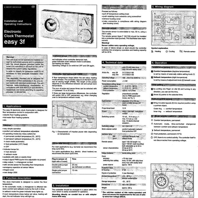
Fitting guide
and
Instructions for use
HEATING MATS
With floor thermostat and Instset
Contents:
Fitting
guide and instructions for use:
|
1. Information for users: |
Page 1 |
|
1.1 Heating mats should only be fitted by registered craftsmen: |
Page 1 |
|
1.2 Functioning: |
Page 1 |
|
1.3 Operation: |
Page 2 |
|
1.4 Maintenance and malfunctions: |
Page 2 |
|
2. For fitters: |
Page 3 |
|
2.1 Installation instructions: |
Page 3 |
|
2.2 Schematic diagram of the underfloor heating: |
Page 5 |
|
2.3 Drawing the laying and room layout plan: |
Page 5 |
|
2.4 Room layout plan showing laying diagrams: |
Page 6 |
|
2.5 Preparation of the floor area to be heated: |
Page 6 |
|
2.6 Laying out the floor heating: |
Page 7 |
|
2.7 Adhesive for heating mat and decking: |
Page 8 |
|
2.8 Covering the floor heating: |
Page 8 |
|
3. Electrical connections: |
Page 10 |
|
3.1 Circuit diagrams: |
Page 10 |
|
4. Technical Data: |
Page 11 |
|
4.1 Measurement record: |
Page 11 |
|
4.2 Large-scale circuit diagrams |
Page 12 |
Fitting guide and instructions for use:
1. Information for users:
· Please store the instructions in a safe place and pass them to the next owner or new user when you move.
· The heating mats are built to VDI standards. These state that these instructions should always be available and should be presented to the technician in the event of work being carried out on the heating.
1.1 Thermofloor should only be fitted by authorised craftsmen:
|
· Once the elements have been fitted and put into operation, the fitter should hand over a room layout plan which should be stored carefully together with the fitting guide and instructions for use. The room layout plan details in which parts of the room the underfloor heating and the sensor protection tube have been installed and where the rating plate is mounted. No plugged screws should be used for fastening purposes in the
area containing the underfloor heating. · An unheated zone of around 50 cm should be planned in around the walls if cupboards with full, flat bases are to be stood there later. Other coverings, e.g. carpets, with a thickness of more than 12mm raise the temperature in the floor and should be avoided. ·
The rating
data of the underfloor heating should be clearly
displayed by the fitter on the inner door of the electrical junction box. |
1.2 Functioning:
|
· The floor heating is a direct underfloor heating system which permits rapid warming of particular cold floor areas, e.g. in kitchens, bathrooms, saunas, hallways or around seating areas. These heating
mats are not intended as the principal source of room heating (the required
heating is normally provided by another heating source), rather they are designed simply to take the chill
off cold floor surfaces. · Depending on the setting, the temperature is generally only raised by a few degrees meaning that the floor heating only consumes electricity for a very short period, making it highly economical to run. In exceptional cases the entire output of the floor heating can be exploited by turning the thermostat up high. · The heating mat is laid directly onto the concrete floor and is contained in a thin 5 to 10mm adhesive layer, allowing it to release its heat quickly to the floor surface and create a pleasant floor temperature. · The floor heating is regulated by an electronic floor thermostat. The sensor is installed in the heating layer and compares the thermostat setting with the floor temperature. The thermostat switches on and off depending on
the heat setting and the floor temperature. Sunshine, heat generated by people, lighting or
other heat sources are detected by the thermostat and taken into account.
The thermostat also serves as a frost safeguard. ·
The thermostat
is self-monitoring, i.e. it automatically switches off the floor heating
in the event of a power cut, a short-circuit
in the sensor or damage to it. |
Page 2
1.3 Operation:
|
· Operation of the floor heating is limited to setting the desired floor temperature on the thermostat knob. The temperature is easy to select using the Celsius scale. The floor temperatures which can be achieved depend on the floor covering (tiles or cork) and the thermal insulation of the concrete base. See also the operating instructions of the thermostat. · The system can be made even more energy-efficient by using a timer thermostat (e.g. EB 52527, or preferably EB 52512). This type
of thermostat allows the floor heating to be switched on and off at set
times to suit your own personal habits. ·
The heating period should be set to come on roughly
30 minutes before actual use (depending on the rating of the heating system)
and should also be set to switch off roughly 30 minutes before the end of
the usage period. |
1.4 Maintenance and malfunctions:
|
· No maintenance is necessary for the heating system.
· In the event of a malfunction, check whether the thermostat is set to heating. · When using a daily or weekly program, ensure that the operating times are correctly set. · Check whether a fuse has blown or the current breaker has tripped. · If there is still no heating, contact your fitter and present him the room layout plan. |
|
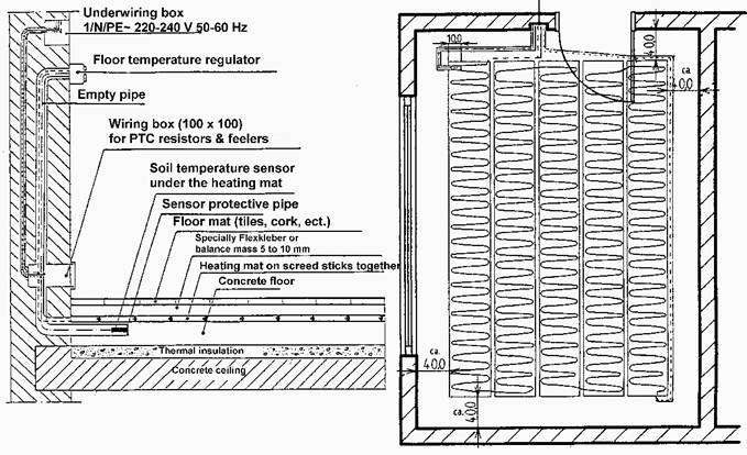
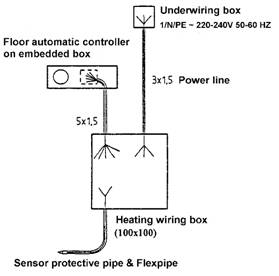
Appendix: The
100x100 connection box should be installed at a height of approx. 30 cm
at the point at which the PTC resistor leads of the heating mat and the
sensor lead reach the wall. If a
number of heating mats are to be installed in a room these can be connected
in parallel in the 100x100 connection box. If many
heating mats are to be laid in a room, meaning that the maximum breaking
capacity of the floor thermostat is exceeded, then the "thumb-size" 16 Amp
relay should be included in the 100x100 connection box. If only
one heating mat is to be laid, e.g. in the bathroom, you
may consider omitting the 100x100 connection box and routing the PTC resistor
and the sensor leads directly up to the floor thermostat. We recommend
fitting the 100x100 connection box at a height of 30 cm. This enables a
new sensor to be inserted if it has to be exchanged. If no
100x100 connection box is fitted and the new sensor lead has to be inserted
from right at the top (floor thermostat positioned at height of 1.3 m),
the sensor lead touches the wall so often in the empty tube (straight down
to the floor) that no force is required to push it around the 90° section
into the horizontal floor level until it comes out right at the front beneath
the heating mats. You
can therefore pull out the old sensor lead, but not insert the new one. If,
however, the 100x100 connection box is installed at a height of 30 cm it
is then simpler to reinsert the sensor if it has to be exchanged. In tiled
rooms (bathroom, shower, etc.), the 100x100 connection box can be fitted
on the other side of the wall (hall, landing etc.), thereby leaving the
bathroom wall intact. The flexitube is used
here as it provides a connection straight through the wall. |
Page 3
2. For fitters:
|
Follow the instructions carefully when fitting. · VDE regulations stipulate that these instructions should always be available and should be presented to the technician in the event of work being carried out on the heating. You should therefore always hand over the room layout plan and these instructions to the customer for safekeeping. ¾ The heating mats contain VDE 0700 heating wires and may be installed in indoor living areas, showers and bathrooms, swimming pools and humid or wet areas for warming the floor - following the appropriate installation instructions. ¾ Only a trained craftsman should carry out fitting and connection of the floor heating and other electrical equipment. DIN VDE 0100 part 520 A3 should be observed here. ¾ Special installation standards also exist for: ¾ Shower rooms and bathrooms: DIN VDE 0100, part 701. ¾ Indoor swimming pools: DIN VDE 0100, part 702. ¾ Humid and wet areas: DIN VDE 0100, part 737. 2.1
Installation
instructions: 1. Select the heating mats on the basis of the area to be heated and the power rating (Watt/m²). Draw the laying plan into the room layout plan (NB. note width of strips - 0.5 or 0.3 m). 2. The floor heating can be laid on any flat surface such as damp-proof chipboard or a simple concrete surface. 3. Note: If the floor heating is to be laid on hot-rolled asphalt, the asphalt should be able to withstand temperatures of roughly 80°C. 4. In sanitation facilities, the areas needed for fitting a floor-mounted toilet, bath, shower unit etc should be worked around. A distance of at least 30mm should be maintained to conducting materials. 5. The heating mat does not need to be installed under fitted cupboards. 6. Position the heating connection box outside the bathroom or toilet (wall tiles make access more difficult). 7. Lay all necessary cabling and empty ducts (see connection diagram). 8.
Fit the sensor protection
tube beneath the heated floor surface and feed the flexitube (PVC section) into the heating connection
box. If the heating mat is too long it can be evenly compressed by 10-15%
lengthways, if necessary, e.g. from 2m down to 1.7m. Heating conductors
should never be laid on top of or right next to each other. The performance
per area then increases correspondingly by 10-15%. Page 4
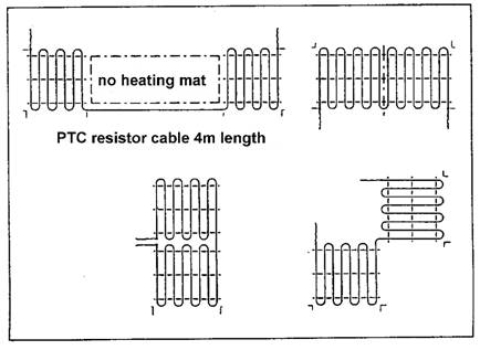
9. Lay out the heating elements on the floor surface to be heated, and make necessary adjustments. Check the volume resistance and conductivity and note these in the measurement report. IMPORTANT: Under no circumstances should the heating wires of the heating mat be shortened. The heating mats should always be laid as entire units. Never heat the heating mat when rolled up. Risk of total damage!! 10. Clean the floor surface and pre-treat with deep solvent primer. There should be no excessive elevations or depressions in the floor. Do not fasten down the floor heating with nails or other metal objects. 11. Take care not to crush or crease the heating mats when laying them. Avoid pulling them too tight. 12. NB. Under no circumstances should the heating conductors of the heating mat be crossed. 13. Use special tile adhesive (flexible adhesive), applying an even 5mm layer with a spreader. 14. Caution. The heating mat should never cross expansion joints in the floor. 15. Do not use any plug screws around the floor heating. 16. Apply the heating mat to the adhesive with the smooth tile side facing downwards and press down gently. 17. Lay the ends of the PTC resistor and PE wires in the tile adhesive bed to the heating connection box and check the volume resistance and conductivity again, noting the result in the measurement report. Wire the heating connection socket as per diagram. When connecting the PTC resistors (phase and neutral conductor), take care not to confuse the PTC resistors with the yellow/green PE lead (the outer protective wire mesh of the PTC resistor is approx. 6 Ohm). Take care when shortening or extending the PTC resistors. After lengthening a PTC resistor, 2 separate cables should continue from the connection or extension point (i.e. the PTC resistor and the yellow-green PE). Instead of laboriously lengthening the PTC resistor (approx. 1 - 1.5m) it is also possible to use "heater strips" at the end of the heating mat for the extension by removing the cotton mesh and utilising the heating wire to extend the PTC resistor. Care is required here, however, as the heating wire must be embedded in flexible tile adhesive up to the shrink sleeve (in which the heating wire is connected to the PTC resistor). Ensure that the heating wire can release its heat to the flexible tile adhesive coating at least up to the sleeve. It is crucial for the heating wire (or cable) can release its heat to the flexible adhesive material. Under no circumstances should the PTC resistor sleeve heating wire be pulled into a empty flexitube where it could overheat and become damaged. Note: Multiple heating mats should only be connected in parallel and not in series. 19. For mechanical protection, always carefully cover the floor heating with a second 5mm layer of special tile adhesive (flexible adhesive). Important: make up the flexible adhesive a little thinner, ensuring that there are no bubbles or hollows in it and that none can form around the heating mat beneath the tiles. Apply the tiles or natural stone covering to this adhesive bed and then check the volume resistance and conductivity again. If the heating wire has been damaged during the laying, it would still be possible to remove the heating mat at this stage and replace it with an undamaged one. 20. When laying parquet, carpet, cork, PVC etc, smooth the adhesive bed with a smoothing disc. 21. Wait two days before carefully heating for the first time. (5°C/day) 22. When laying parquet, carpet, cork, PVC etc, use a primary coat as a bonding agent. Follow the manufacturer's instructions. 23. Do not cover heated floors with carpets which are thicker than 12mm (risk of heat accumulation). Items of furniture with flat, solid bases should not be stood on heated surfaces. 24. Instruct the owners on how to use the floor heating and hand over the room layout plan together with the laying diagram. Display a note in the electrical junction box (electrical underfloor heating), specifying which rooms are heated. |
Page 5
|
2.2 Schematic diagram of the underfloor heating: |
Example of laying and room layout plan: |
|
|
2.3 Drawing the laying and room layout plan:
|
· Before laying the heating mat, the following points should be noted on the room lyout plan. The points in the room in which the following are located: ¾ the underfloor heating ¾
¾ the floor thermostat and the routing of the sensor protection tube ¾
¾ the PTC resistors (phase, neutral, PE conductors) of the heating mat. ¾ In showers and bathrooms the areas to be occupied by bathtubs, shower cubicles, floor-mounted toilets etc should be left free. Leave a minimum gap of 30 mm to conducting materials. A distance of 30 to 50 cm can be left to the walls (depending on if these areas are to be covered later with flat-based floor-standing furniture). After installation, the room layout plan should then be handed over to the owner for safekeeping. |
Page 6
2.4 Room layout plan showing laying diagrams:
|
|
2.5 Preparation of the floor area to be heated:
|
· First check the floor surface to make sure there are no excessive elevations or depressions which could damage the heating mat. If there are any, they should be carefully removed. ·
Before fitting the heating mat, an embedded junction
box should be mounted in a suitable position (typically in the hall outside
the bathroom, due to the tiles), into which both the PTC resistors and
the sensor protection tube can easily be fed. An electrical connection with
3x1.5 mm² connection leads should be laid into the embedded junction box.
Lay a 5x1.5 mm² connection cable from the embedded junction box to the
place whether the electronic floor thermostat is to be fitted. ·
Important: Feed the PTC resistors into the embedded box; the floor thermostat should be laid in a separate Ø 13 mm sensor protection tube (it is best to lay the sensor and the sensor protection tube at the same time). The sensor and sensor protection tube should be laid on the concrete so that it is directly beneath the area which will later be covered by the floor heating (as shown in room layout plan). The
PTC resistor leads of the floor heating and the thermostat sensor should
not be laid in the same conduit. Page 7
· Feed the thermostat floor sensor into the sensor protection tube and ensure that the end of the sensor (in the tube) is between two heating wires when you lay the mats afterwards. If an open
sensor protection tube is used, this should be sealed with a plug to ensure
that no tile adhesive can enter. ·
Lay the sensor
leads so that neither cross nor touch the heating wires. |
2.6 Laying out the floor heating:
|
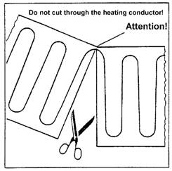
· With the heating wire on top, spread out the heating mat in the laying area as per the room layout plan. The fabric can be cut to the required shape using scissors (Caution: only cut the fabric and not the heating wire). ·
Important note: The heating wire of the underfloor heating should never be shortened. Take care not to damage the heating wire when cutting the fabric. |
|
|
|
|
· At the point where the fabric has been cut, the heating wire can now be carefully bent and laid parallel to the first strip. Do not fold the heating wire, however; the minimum bending radius is 20 mm. ·
Important note: Never lay the heating strips on top of each other. There should always be a minimum distance of 3 cm between the heating wires. The heating mats should be laid over the entire area in the same way. ·
Guarantee note: Measure the conductivity of the heating mat using a multitester (see technical specifications) and note the reading on the room layout plan and in the junction box. · Important: Multiple heating mats should only be connected in parallel and not in series. During laying of the floor heating, the PTC resistors should be laid in the adhesive bed and fed to the heating connection box (preferably in a separate flexitube leading from the wall corner to the heating connection box). |
Page 8
2.7 Adhesive for heating mat and decking:
|
· Flexible adhesives which are heat resistant up to 80°C are suitable for holding the heating mat and laying the tiles. They also offer mechanical protection when using floorings such as carpet, PVC, cork etc. ·
A. Adhesive for
heating mats and ceramic plates (tiles) or natural stone plates: PCI-Flexmörtel, special tile adhesive for balcony, terrace and underfloor heating Adhesive bed up to max. thickness of 5 mm, -20°C to 80°C, drying time approx. 4.5 hours PCI Flexmörtel, rapid special tile adhesive for balcony, terrace and underfloor heating Adhesive bed up to max. thickness of 5 mm, -20°C to 80°C, drying time approx. 2-3 hours
or Knauf products (ask your Knauf retailer) ·
B. Surface protection
for deckings, carpet, PVC, cork etc. To provide mechanical protection when laying carpet, PVC, cork etc., the heating mat should be covered with a 5 to 10 mm protective layer. We recommend: PCI Periplan 10, up to 10mm thickness PCI Periplan 20, up to 20mm thickness ·
Use a multimeter to check continually whether the heating
mat is still conducting (resistance as given in technical specifications)
when laying. |
2.8 Covering the floor heating:
|
·
A. Laying tiles
and natural stone plates: Follow the instructions of the adhesive manufacturer very carefully. Apply the
adhesive to the floor using a spreader (3-4 mm). Lay the heating mat with
the heating wire facing upwards (smooth side downwards) into this adhesive
bed and press it down carefully using a smoothing disc. Carefully smooth any squeezed-through adhesive. Then cover the top of the heating mat again with a layer of special flexible adhesive (4-6 mm spreader) into which the tiles or natural stone plates are laid. During the laying process ensure that the temperature sensor is laid between heating wires (as per room layout plan). Feed the PTC resistor wires along the floor in the adhesive bed to the heating connection box and feed them into the heating box through a prepared flexitube. When pointing the tiles, use a flexible sealing compound. Page 9
·
B. Laying deckings such as carpet, PVC, cork, parquet: Once the
heating mat has been laid as described above and covered with a second layer
of special flexible adhesive, carefully smooth this mechanical protective
layer with the smoothing disc. If necessary, this dry adhesive surface can be recoated after 24 hours to make the surface smooth and flat (PCI Periplan). Follow the filler manufacturer's instructions very carefully. Preparation of the surface depends on the type of special adhesive required e.g. of cork, PVC, parquet or carpet. A primer should always be used as an undercoat for fixing and for improving the bond. Depending on the amount of dampness in the base, do not start laying the decking until after at least three days. Only use suitable deckings which are compatible with floor heating. Note the following thermal conductance values: ¾ lvalue = 0.14 W/(m.K) for parquet, max. 16mm thickness ¾ lvalue = 0.09 W/(m.K) for carpet, max. 20mm thickness ¾ lvalue = 0.08 W/(m.K) for cork, max. 10mm thickness ¾ lvalue = 0.23 W/(m.K) for PVC, max. 10mm thickness ¾ lvalue = 1.00 W/(m.K) for tiles, max. 30mm thickness ¾ lvalue = 1.00 W/(m.K) for natural stone, max. 30mm thickness |
|
· Important: The
heating wires should neither touch the PTC resistor wires nor cross them. Check
the Ohm values continually while laying and compare them with the first
reading
If
the heating mat is damaged, this should then be recognised immediately and
the faulty heating mat can be exchanged for an undamaged one. Leave
notification alerting other craftsmen that electrical floor heating has
been installed in the room. |
Page 10
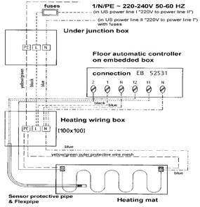
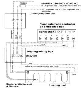
3. Electrical connections:
|
· The heating mat should be fitted electrically by a qualified electrician in accordance with the current VDE regulations and these fitting instructions. ·
The contact holes of all poles of the floor heating
connections should be at least 3mm from the mains. Circuit
breakers, fuses and distributor contactors are suitable disconnection devices. · The regulations of the local electricity provider should be observed. The heating circuit should also feature a 30 mA circuit breaker, especially in showers and bathrooms, to ensure protection and safety against dangerous electrical shocks (it is normally sufficient if the apartment or at least the bathroom junction box from where the heating current originates is fitted with a circuit breaker). Connect the floor heating as shown in the diagrams. Make sure the PE wire (yellow/green) is properly connected. · Several heating mats can be connected to a single electronic thermostat. Important:
Multiple heating mats
should only be connected in parallel and not in series.
· Do not exceed the maximum switched current (switching capacity) given in the technical specifications. |
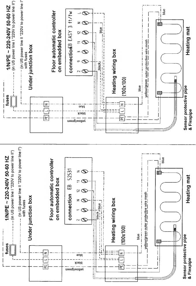
3.1 Circuit diagrams:
|
e.g. laying cables
|
After work: Once the work has been completed a rating plate containing the Ohm value should be clearly displayed in the junction box. Make a note of this junction box in the room layout plan and hand these fitting and operating instructions to the owner for safekeeping. Start-up: After 48 hours the floor heating can be gradually heated up (5°C per day). |
|
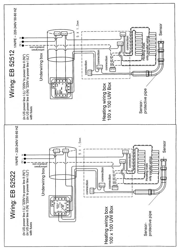
Wiring: EB 52531
|
Wiring: EB 52527 / 28
|
Page 11
3. Technical Data:
4.1 Measurement record:
|
Item no.: |
Power: Watt/item |
Dimensions: L x W in m: |
Area: m² |
Ohm value/heating mat approx. |
Voltage: 1/N/PE |
Three values: Room: W |
|
WT PV-3L-5N 160 Watt /m² 0.3m width 3mm thickness |
||||||
|
WTL1,216 |
192 Watt |
4.0 x 0.3 |
1 |
276 W |
230V/50Hz |
|
|
WTL2,416 |
384 Watt |
6.7 x 0.3 |
2 |
138 W |
230V/50Hz |
|
|
WTL3,616 |
576 Watt |
10.0 x 0.3 |
3 |
92W |
230V/50Hz |
|
|
WT PV-3-10N 120 Watt /m² 0.5m width 3mm thickness |
||||||
|
WTN112 |
120 Watt |
2 x 0.5 |
1 |
441 W |
230V/50Hz |
|
|
WTN1,512 |
180 Watt |
3 x 0.5 |
1,5 |
294 W |
230V/50Hz |
|
|
WTN212 |
240 Watt |
4 x 0.5 |
2 |
220 W |
230V/50Hz |
|
|
WTN312 |
360 Watt |
6 x 0.5 |
3 |
147 W |
230V/50Hz |
|
|
WTN412 |
480 Watt |
8 x 0.5 |
4 |
110 W |
230V/50Hz |
|
|
WTN512 |
600 Watt |
10 x 0.5 |
5 |
88 W |
230V/50Hz |
|
|
WTN612 |
720 Watt |
12 x 0.5 |
6 |
73 W |
230V/50Hz |
|
|
WTN712 |
840 Watt |
14 x 0.5 |
7 |
63 W |
230V/50Hz |
|
|
WTN812 |
960 Watt |
16 x 0.5 |
8 |
55 W |
230V/50Hz |
|
|
WT PV-S-10N and WT PV-3L-5N 160 Watt /m² 0.5m
width 3mm thickness |
||||||
|
WTL/WTN116 |
160 Watt |
2 x 0.5 |
1 |
331 W |
230V/50Hz |
|
|
WTL/WTN1,516 |
240 Watt |
3 x 0.5 |
1.5 |
220 W |
230V/50Hz |
|
|
WTL/WTN216 |
320 Watt |
4 x 0.5 |
2 |
165 W |
230V/50Hz |
|
|
WTL/WTN316 |
480 Watt |
6 x 0.5 |
3 |
110 W |
230V/50Hz |
|
|
WTL/WTN416 |
640 Watt |
8 x
0.5 |
4 |
83 W |
230V/50Hz |
|
|
WTL/WTN516 |
800 Watt |
10 x 0.5 |
5 |
66 W |
230V/50Hz |
|
|
WTL/WTN616 |
960 Watt |
12 x 0.5 |
6 |
55 W |
230V/50Hz |
|
|
WTL/WTN716 |
1120Watt |
14 x 0.5 |
7 |
47 W |
230V/50Hz |
|
|
WTL/WTN816 |
1280Watt |
16 x 0.5 |
8 |
41 W |
230V/50Hz |
|
|
FH 160Watt /m² 0.5m width 2mm thickness |
||||||
|
FH 116 |
160 Watt |
2 x 0.5 |
1 |
330 W |
230V/50Hz |
|
|
FH 1,516 |
240 Watt |
3 x 0.5 |
1.5 |
220 W |
230V/50Hz |
|
|
FH 216 |
320 Watt |
4 x 0.5 |
2 |
165 W |
230V/50Hz |
|
|
FH 2,516 |
400 Watt |
5 x 0.5 |
3 |
132 W |
230V/50Hz |
|
|
FH 316 |
480 Watt |
6 x 0.5 |
3 |
110 W |
230V/50Hz |
|
|
FH 416 |
640 Watt |
8 x 0.5 |
4 |
83 W |
230V/50Hz |
|
|
FH 516 |
800 Watt |
10 x 0.5 |
5 |
66 W |
230V/50Hz |
|
|
FH 616 |
960 Watt |
12 x 0.5 |
6 |
55 W |
230V/50Hz |
|
|
FH 716 |
1120Watt |
14 x
0.5 |
7 |
47 W |
230V/50Hz |
|
|
FH 816 |
1280Watt |
16 x 0.5 |
8 |
41 W |
230V/50Hz |
|
|
FH 916 |
1440Watt |
18 x 0.5 |
9 |
37 W |
230V/50Hz |
|
|
Item no.: |
Power: Watt/item |
Dimensions: L x W in m: |
Area: m² |
Ohm value/heating mat approx. |
Voltage: 1/N/PE |
Three values: Room: W |
|
FH Twin 160Watt /m² 0.5m width 2mm thickness |
||||||
|
FHT 116 |
160 Watt |
2 x 0,5 |
1 |
330 W |
230V/50Hz |
|
|
FHT 1,516 |
240 Watt |
3 x 0.5 |
1.5 |
220 W |
230V/50Hz |
|
|
FHT 216 |
320 Watt |
4 x 0.5 |
2 |
165 W |
230V/50Hz |
|
|
FHT 2,516 |
400 Watt |
5 x 0.5 |
3 |
132 W |
230V/50Hz |
|
|
FHT 316 |
480 Watt |
6 x 0.5 |
3 |
110 W |
230V/50Hz |
|
|
FHT 416 |
640 Watt |
8 x 0.5 |
4 |
83 W |
230V/50Hz |
|
|
FHT 516 |
800 Watt |
10 x 0.5 |
5 |
66 W |
230V/50Hz |
|
|
FHT 616 |
960 Watt |
12 x 0.5 |
6 |
55 W |
230V/50Hz |
|
|
FHT 716 |
1120 Watt |
14 x 0.5 |
7 |
47 W |
230V/50Hz |
|
|
FHT 816 |
1280 Watt |
16 x 0.5 |
8 |
41 W |
230V/50Hz |
|
|
FH T916 |
1440 Watt |
18 x 0.5 |
9 |
37 W |
230V/50Hz |
|
|
TF-S-R-3L 300 Watt /m² 0.5m width 6mm thickness |
||||||
|
TFR130 |
300 Watt |
2 x 0.5 |
1 |
176 W |
230V/50Hz |
|
|
TFR1,530 |
455 Watt |
3 x 0.5 |
1.5 |
118 W |
230V/50Hz |
|
|
TFR230 |
600 Watt |
4 x 0.5 |
2 |
88 W |
230V/50Hz |
|
|
TFR330 |
900 Watt |
6 x
0.5 |
3 |
59 W |
230V/50Hz |
|
|
TFR430 |
1200 Watt |
8 x 0.5 |
4 |
44 W |
230V/50Hz |
|
|
TFR530 |
1500 Watt |
10 x 0.5 |
5 |
35 W |
230V/50Hz |
|
|
TFR630 |
1800 Watt |
12 x 0.5 |
6 |
29 W |
230V/50Hz |
|
|
TFR730 |
2100 Watt |
14 x 0.5 |
7 |
25 W |
230V/50Hz |
|
|
TFR830 |
2400 Watt |
16 x 0.5 |
8 |
22 W |
230V/50Hz |
|
|
Thermofloor S 160 Watt /m² or 200 Watt/m² 0.5m width 4mm thickness |
||||||
|
TFS116/TFS120 |
160W/200W |
2 x 0.5 |
1 |
330 W/264 W |
230V/50Hz |
|
|
TFS216/TFS220 |
320W/400W |
4 x 0.5 |
2 |
165 W/132 W |
230V/50Hz |
|
|
TFS316/TFS320 |
480W/600W |
6 x 0.5 |
3 |
110 W/88 W |
230V/50Hz |
|
|
TFS416/TFS420 |
640W/800W |
8 x 0.5 |
4 |
82 W/66 W |
230V/50Hz |
|
|
TFS516/TFS520 |
800/1000W |
10 x 0.5 |
5 |
66 W/53 W |
230V/50Hz |
|
|
TFS616/TFS620 |
960/1200W |
12 x 0.5 |
6 |
55 W/44 W |
230V/50Hz |
|
|
TFS720 |
1120/1400W |
14 x 0.5 |
7 |
47 W/38 W |
230V/50Hz |
|
|
TFS820 |
1280/1600W |
16 x 0.5 |
8 |
41 W/33 W |
230V/50Hz |
|
|
TFS916/TFS920 |
1440/1800W |
18 x 0.5 |
9 |
37 W/29 W |
230V/50Hz |
|
|
WTTFS-10N, WTTF-3L-10N 200
W /m² or 250 W/m² 0.5m width 4.5mm thickness |
||||||
|
TFS220/TFL225 |
400W/500W |
4 x 0.5 |
2 |
132 W/106 W |
230V/50Hz |
|
|
TFS320/TFL325 |
600W/750W |
6 x 0.5 |
3 |
88 W/75 W |
230V/50Hz |
|
|
TFS420/TFL425 |
800/1000W |
8 x 0.5 |
4 |
66 W/53 W |
230V/50Hz |
|
|
TFS520/TFL525 |
1000/1250W |
10 x 0.5 |
5 |
53 W/42 W |
230V/50Hz |
|
|
TFS620/TFL625 |
1200/1500W |
12 x 0.5 |
6 |
44 W/35 W |
230V/50Hz |
|
|
TFS820/TFL825 |
1600/2000W |
12 x 0.5 |
8 |
33 W/26 W |
230V/50Hz |
|
TFS1020/TFL1025
|
2000/2500W |
14 x 0.5 |
10 |
26 W/21 W |
230V/50Hz |
|
|
TFS1220/TFL1225 |
2400/3000W |
16 x 0.5 |
12 |
22W/18W |
230V/50Hz |
|
|
TFS1420/TFL1425 |
2800/3500W |
18 x 0.5 |
14 |
19 W/15 W |
230V/50Hz |
|
|
TFS1620/TFL1625 |
3200/4000W |
16 x 0.5 |
16 |
17 W/13 W |
230V/50Hz |
|
|
TFS1820/TFL1825 |
3600/4500W |
18 x 0.5 |
18 |
15 W/12 W |
230V/50Hz |
|